Tracel Industrial Battery
Charging Rectifier
recT Product Line
The recT line battery chargers/rectifiers are electric power conversion equipment used mainly in substations in generation, transmission and energy distribution sectors.
These rectifiers were 100% developed by Tracel with the following characteristics:
- IGBT technology with 12-pulse rectification;
- Peak power factor and efficiency;
- High grid and M-G set input harmonic distortion tolerance;
- Densely integrated control, supervisor and monitoring unit, with HMI and fewer electronic component boards;
- Special projects according to the customer’s request.


Tracel has been exceeding expectations in the domestic market with its unique patented technology, with imported power components we build the charging battery rectifier that meets client demands. Each unit is composed of the following subsystems:
Isolating Transformer: traditional (with grain-oriented cores and copper wiring) or special high-frequency transformers with low loss ferrite material, and little to no noise coupling between the primary and secondary.
Formidable output inductor with a unique magnetic core that greatly reduces inductor size and used copper material.
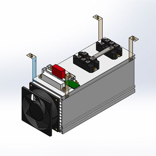

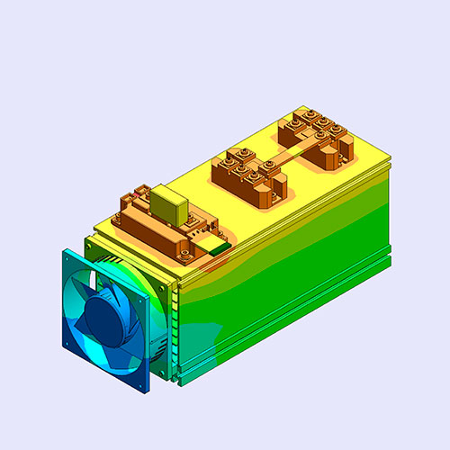
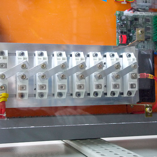
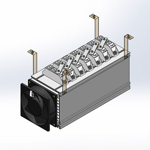
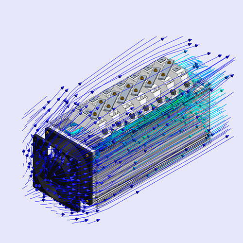
Power Module: Input rectifying bridge design, precise capacitor and switch selection, and custom cooling and heat sink projects through mathematical modeling of thermal losses in switches, diodes, and other components; advanced simulations and trial testing validation.
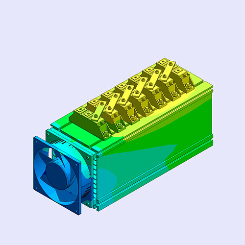
Diode bias module: Bypass Diode and relay design,validated through thermal loss calculation from power components; advanced simulations and trial testing validation that complement component selection, according to the cooling and heat sink configuration.
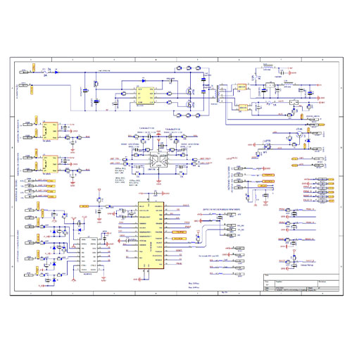
Control Module: Electronic circuit board design, consisting of specification analysis, computer simulation, and electronic board routing*¹, electronic component mounting, and application-specific software development involving low-level programming of advanced microcontrollers and digital signal processors.
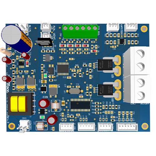
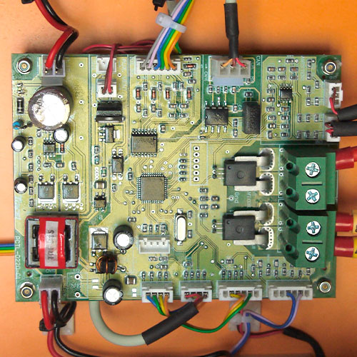
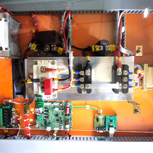
Electrical and mechanical projects that have integrated all industrialized Tracel equipment/components developed through CAD software, and physical mounting and testing.

Datasheet
| AC Input | |
| Voltage | 220 / 380 / 440 Vca +/- 10% (other voltages upon request) |
| Frequency | 60 Hz ou 50 Hz +/- 5% |
| Power system | Single-phase, Two-phase, and Three-phase |
| Power factor | > 0,92 (standard) |
| Efficiency | > 0,85 (standard) |
| Filtering | Harmonic filter |
| Protection/ Routing |
Relay |
| Commands | |
| On and Off | Two-position switch Rectifier Power On/Off in floating mode operation |
| Operation mode toggle | Push button for floating mode toggle to load operation, with automatic revert to floating mode |
| OPTIONAL | Floating voltage adjust according to battery bank temperature |
| DC Rectified Output (Battery Bank) | |||||
| Voltage | 12V | 24V | 48V | 125V | 250V |
| Number of Batteries | 1 de 12V ou 6 de 2V | 2 de 12V ou
12 de 2V |
4 de 12V ou
24 de 2V |
10 de 12V ou 60 de 2V | 20 de 12V ou
120 de 2V |
| Floating mode voltage | 13,2V | 26,4V | 52,8V | 132V | 264V |
| Ripple | ≤ 2% without batteries and ≤ 1% with batteries | ||||
| Recharge voltage | 14,4V | 28,8V | 57,6V | 144V | 388V |
| Discharge voltage (2.0V) | 12V | 24V | 48V | 120V | 240V |
| Minimum discharged voltage (1.75V) | 10,5V | 21V | 42V | 105V | 210V |
| Battery capacity | C10 (Ah/10h) or recommended by the manufacturer | ||||
| DC Consumer Output | |||||
| Nominal voltage | 12 V – 24 V – 48 V – 125 V ou 250 V | ||||
| Maximum output voltage *¹ | 13,2 V – 26,4 V – 52,8 V – 132V ou 264 V | ||||
| Nominal Current (In) | 5 to 500 A (other currents upon request) | ||||
| Output current limit | Adjustable from 50 % up to 100% of In | ||||
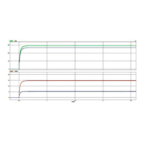
| Static regulation | ≤ +/-1 % for variations from 10 % to 105 % of In | ||||
| Dynamic regulation | +/-10 % overshoot for step load from 10 % to 100 % of In | ||||
| Ripple | <1 % without batteries | ||||
| Yield | 12V | 24V | 48V | 125V | 250V |
| ≥ 70 % | ≥ 75 % | ≥ 80 % | ≥ 85 % | ≥ 90 % | |
| Isolation | > 5 mega Ohms | ||||
Nota *1: Para equipamentos com Unidade Conversora (UC) ou Unidade de Diodo de Queda (UDQ).
| Operating Conditions | |
| Time | Continuously |
| Temperature range | 0 °C a 40°C |
| Relative humidity | 0 % to 95 % without condensation |
| Altitude | Up to 1,000 m from sea level |
| Cooling | Forced ventilation |
| Noise level | > 60dB |
| Protection | |
| Relays | Grid, batteries, and consumer *¹ |
Note *1: Optional manual bypass relay (maintenance) and/or manual bypass for the UDQ or UC modules.
| Mechanical aspects | |
| Enclosure | Self-sustained |
| Coating | Epoxi resin with electrostatic finish |
| Color | RAL 7032 |
| Ingress Protection | IP42 (special requirements upon request) |
| Remote interface | |
| Standard | NO Dry contacts |
| RS232 Communication interface (configuration) | |
| Optional | RJ45 Interface with Ethernet protocol (TCP/IP) |
| Other requirements upon request | |
| Local Signaling – Standard | ||||
| LED | State | Warning | Combined LED and Relay States | Warning |
| Red (GRID) | Off | Grid absent | Red + Yellow LEDs On | Battery bank charged and device activated |
| On | Grid available | Green LED On + Yellow LED Flashing |
Battery bank charging OR discharging AND device activated | |
| Green (RET STATUS) | Off | Device Off | Green LED On + Red LED Flashing |
Battery bank discharging and device deactivated |
| On | Device On | Red + Green LEDs Flashing | Battery bank discharging and device failure | |
| Flashing | Device failure | Red LED Off + Green LED Flashing |
Battery bank discharging and device failure | |
| Yellow (BATTERIES) | Off | Discharged battery bank | ||
| On | Charged battery bank | |||
| Flashing | Battery bank close to discharge limit | |||